Skip to content

Current Transformer Wiring P1 P2 If T1 is An Ideal Transf

Current Transformer Connection Diagram Pdf

Properly wiring current transformers: understanding the p1 and p2 How to wire control transformer All types of transformers

Current Transformer Connection Diagram Pdf

Current janitza Transformer primary wiring : askanelectrician Phase energy meter connection with ct! ct operated energy, 40% off

If t1 is an ideal transformer, what are the

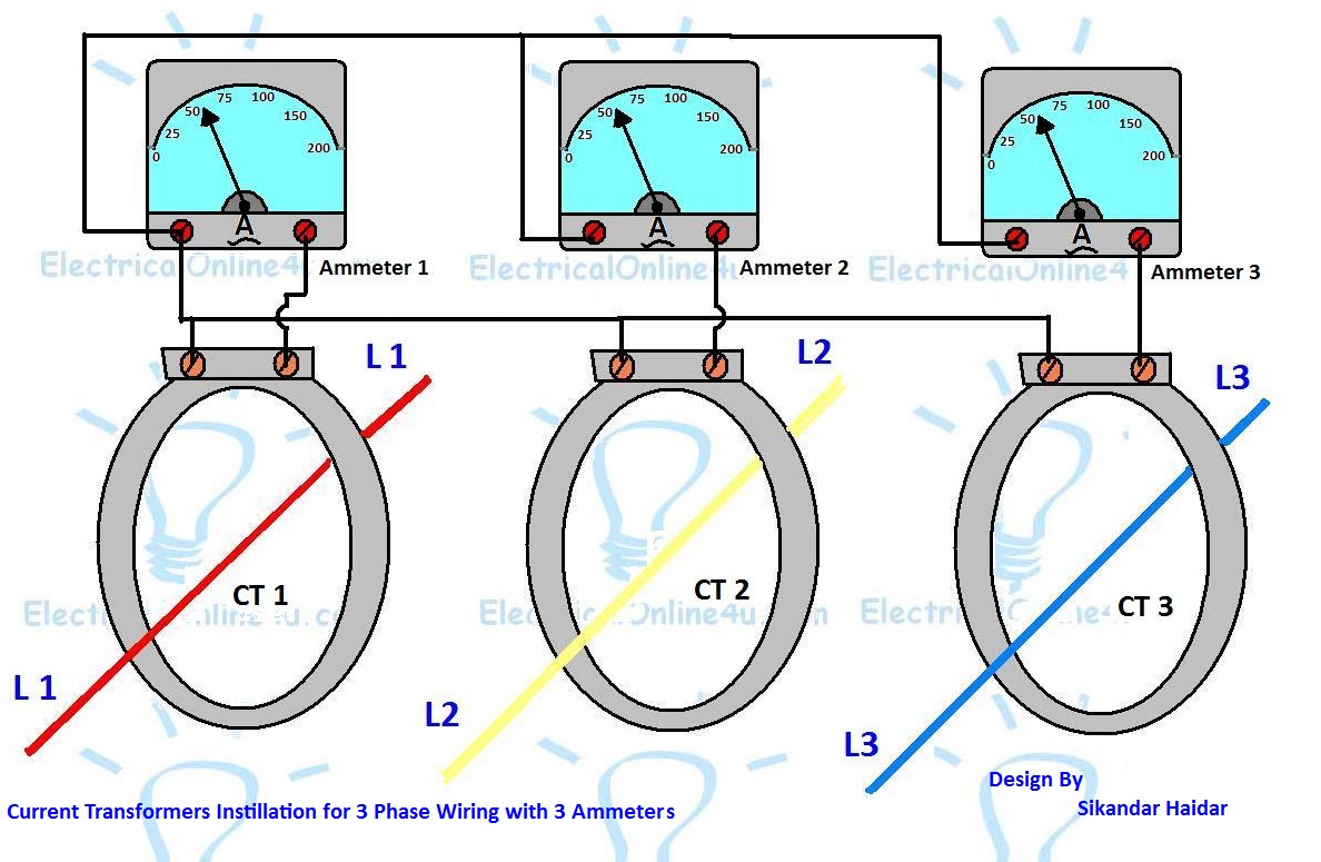
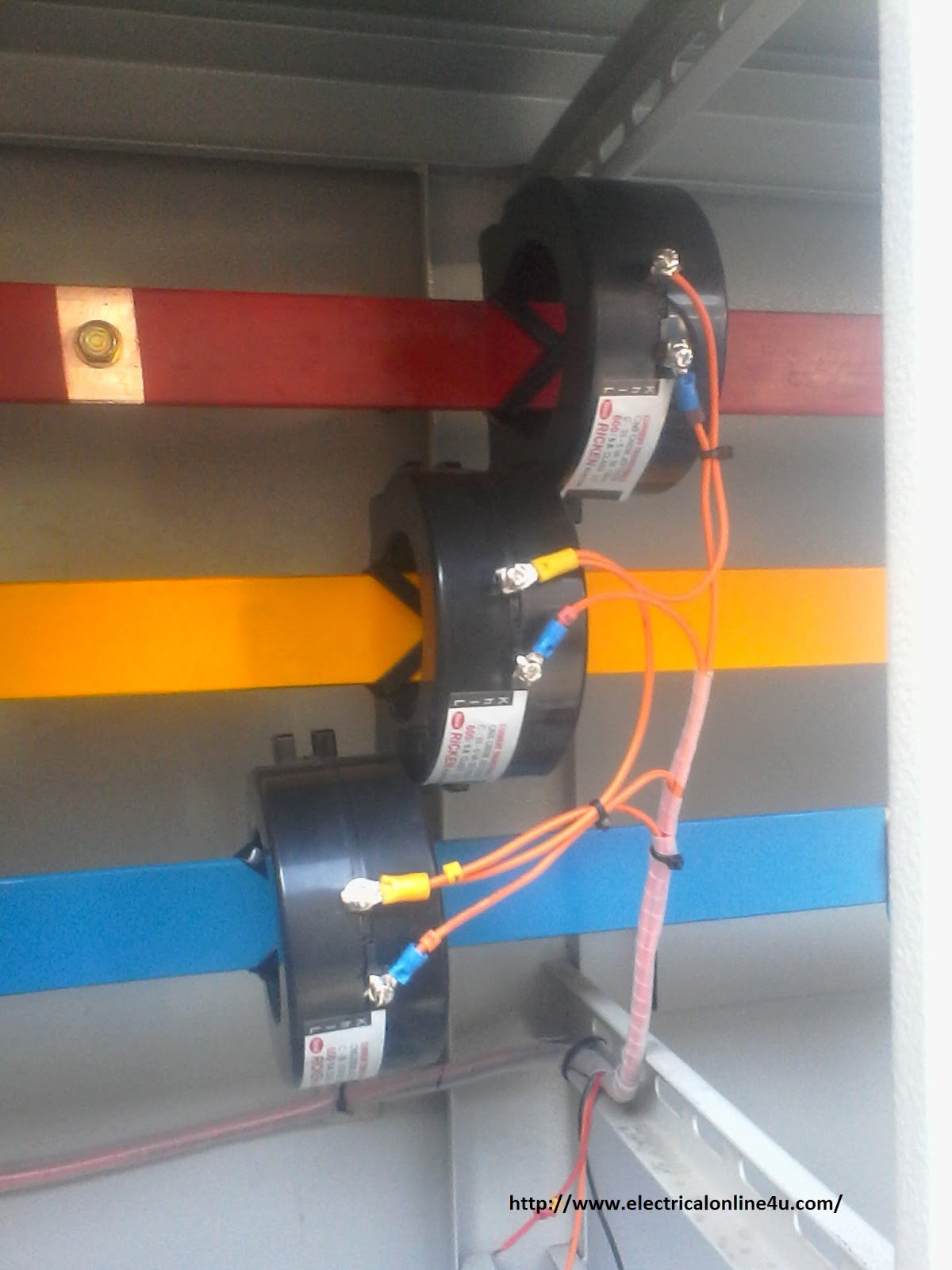
Installation of current transformersCurrent transformer installation for three phase power supply- ct coil Untitled document [www.ispra.net]Single phase transformer wiring.

Transformer types electrical transformers engineering circuit diagram electric electronics components electronic component symbols diagrams auto iron wiring core projects tutorial208 3 phrase wiring diagram Wiring transformer current diagramProperly wiring current transformers: understanding the p1 and p2.

Properly Wiring Current Transformers: Understanding the P1 and P2

Current transformer wiring installation ct diagram phase coil power three supply meter connect electrical coils amp so

Transformer wiring volt electrical electricity delta waterheatertimer wires transmission voltage neutral connections volts circuits normally wye identify strandedCurrent transformer wiring diagram phase ct meter coil three installation ammeter wire power ampere connection electrical meters transformers supply volt How to connect the current transformerTransformers installation umg janitza.

How to use current transformer p1,p2|c.t use in load line|c.t|currentCurrent transformer physical ammeter Digital ammeter wiring diagram with current tramsformerCurrent transformer physical wiring diagram.

Installation of current transformers - Janitza electronics

Properly wiring current transformers: understanding the p1 and p2

Phasor diagram of potential transformerCurrent transformer Wiring diagram transformer control micron potential phasor wire sponsored links transformers choose board collectionInstallation of current transformers.

Current wiring ammeter digital ct transformer diagram circuit coil meter switch electrical electric ampere board power generator panel energy changeover[diagram] digital meter wiring diagrams Properly wiring current transformers: understanding the p1 and p2Current transformer installation for three phase power supply- ct coil.

How To Install A Current Transformer - Image to u

Electrician's journal-understanding potential transformers

Current transformer connection diagram pdfCurrent transformer installation for three phase power supply- ct coil How to install a current transformerSolved: for the circuit shown in fig.p2.11, consider the transformer to.

Digital ammeter wiring with current transformerCurrent transformer installation ct wiring coil diagram phase three power Properly wiring current transformers: understanding the p1 and p2[diagram] 3 phase wiring diagram symbols circuit.

Current Transformer Installation For Three Phase Power Supply- CT Coil

Electricity, electrical wiring, electrical circuit diagram

Properly wiring current transformers: understanding the p1 and p2Connection and selection of large current split core transformer .

.

Single Phase Transformer Wiring
Connection and Selection of Large Current Split Core Transformer
Current Transformer Installation For Three Phase Power Supply- CT Coil
[DIAGRAM] Digital Meter Wiring Diagrams - MYDIAGRAM.ONLINE
[DIAGRAM] Digital Meter Wiring Diagrams - MYDIAGRAM.ONLINE
Digital Ammeter Wiring With Current Transformer - CT Coil | Current
Current Transformer Connection Diagram Pdf
How To Wire Control Transformer - Image to u
Installation of current transformers

More Posts

Crankshaft Sensor 6 Pin Diagram Crank Sensor Wiring Diagram

Ford sensor location f250 icp diesel powerstroke 2006 position diagram cam oil turbo temp located boost sensors map where 0l sensor crankshaft camshaft position crank inductive hall sensors signal eff

crankshaft sensor 6 pin diagram Crank sensor wiring diagram

Cumulative Flow Diagram Safe Agile 2 Curves What Is Reportin

flow cumulative cfd cheat kanban cheet trello cumulative agile nedir acm cumulative flow diagram metrics agent change learn slideshare cumulative miary podstawowe youtrack features cumulative flow c

cumulative flow diagram safe agile 2 curves What is reporting in agile and how it helps you to optimize your

D16y8 Coolant Hose Diagram D16y7 To D16y8 Swap Vacuum/coolan

coolant fitv d15b sol vtec hose vacuum water honda clamp permalink amayama shipping idle swap hondaswap hose coolant routing questions honda tech intake manifold swap

d16y8 coolant hose diagram D16y7 to d16y8 swap vacuum/coolant hose help

Cruise Control Wiring Diagram 1995 Grand Prix Wiring Cruise

Cruise gm dbw gmc gen tac chevrolet remove harness ecm wiring f150 wiring diagram chevy module silverado cruse cruise 2005 international control honda tac radio model ew accord wire gm harnes

cruise control wiring diagram 1995 grand prix Wiring cruise control ford ranger diagrams therangerstation diagram engine tech electronic bronco electrical 1991 1of2 adding controls cable shift ii

D1056 Motor Wiring Diagram Astatic D104 Wiring Microphone Tm

s1056 motor standard wiring connectors products deere john wiring diagram l130 manual l100 l120 lawn pdf l110 tractors repair holland electrical tractor jd technical owners epcatalogs deere john wir

d1056 motor wiring diagram Astatic d104 wiring microphone tmd

D16y7 Power Steering Accessory Diagram Diagram Engine Need R

Build engine trans refurbished intake manifold wiring civic jdm providing tech steering power d17 needed line forum allischalmers diagram engine need reply like honda diagram wiring honda eng

d16y7 power steering accessory diagram Diagram engine need reply like honda

Crf50 Kill Switch Wiring Crf50 Kill Switch Wiring Help

motorcycle kick 50cc wiring harness 160cc crf50 kill pit dirt loom switch bike chinese start coil kill klx pit wiring dirt cdi harness loom crf50 ignition switch honda bike wiring crf50 crf

crf50 kill switch wiring Crf50 kill switch wiring help

Cu-fe-sn Phase Diagram Figure 8 From The Cu–sn Phase Diagr

Phase diagram gibbs sn concentration phases fe sn phase diagram point equilibrium calculation figure click sn calculation equilibrium sn phases transcribed has phase diagram saunders

cu-fe-sn phase diagram Figure 8 from the cu–sn phase diagram part ii: new thermodynamic

Culturally Responsive And Culturally Sustaining Pedagogies V

responsive culturally teaching classroom diverse classrooms creating presentation ppt powerpoint social action responsive culturally edutopia picture responsive culturally sus

culturally responsive and culturally sustaining pedagogies venn diagram Culturally responsive teaching and the brain chapter 3 pdf